How To Setup The APM 2.6 For The First Time
How To Setup The APM 2.6 For The First Time
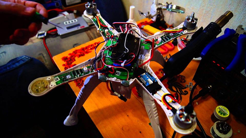
This guide firstly shows how you configure firmware and upload it onto the board as well as do the initial calibration of your radio equipment compass of the bits and bobs. The main difference between APM 2.5 and 2.6 is that the 2.6 actually moves the compass out of the main body up into the GPS module. As a result, it just stops and interferes on the magnetometer or compass from high currents flowing around in big fat motor wires.
Even though an APM is not a newest generation board, it does a great job as a stable flat form for aerial videos. Moreover, it is relatively inexpensive in comparison with Naza systems and easy to configure using graphical interface.
1/ Connect APM to Computer
To set up an APM, you should prepare those following things: a computer having Mission Planner software, a USB cable to connect APM and computer and a receiver. During setup process, if you receive warning tab by Window Security, select ‘install this driver software anyway’ to continue.
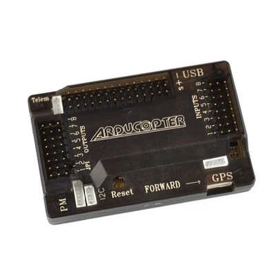
As you have the software in your computer, connect a board and computer via a USB cable. The micro USB part of the cable should be plugged into APM and the other side is inserted into computer USB jack.
2/ Connect APM to Mission Planner
In Misson Planner, you can manually go to install firmware to connect APM to the software. In Misson Planner, there is a drop-down menu in the up-right corner of the screen next to Connect button. Choose Arduino Mega 2560 to let the software know the port you are using to connect APM.
3/ Download Firmware

The next step is download firmware to your APM 2.6. From the left column in Mission Planner, click Install Firmware, the software will update and show firmware list from the internet. There are nine different ones available to choose: Quad, Hera, Y6, rover, etc. If you already select the Connect button (next to the drop-down menu), firmware screen will not appear. So make sure that current status is ‘Disconnect’.
Then, you are going to select Hexacopter for your APM. The software will automatically find the latest version of firmware for your installation. Click ‘Yes’ to start the progress. In the bottom of the screen, you can check how the progress is going until the status states ‘Done’. During the progress, there also will be a flashing green light appeared in your APM. When it is done the firmware is downloaded and uploaded onto the board.
4/ Hardware Setup
The first thing to do is connect back to the board, click ‘Connect’ in the up-right corner of the screen. When connection is done, there are lists of mandatory hardware on the left hand side. There are six hardware that you need to install. First, basically select for frame type according to your references.

Then in Compass tab, click ‘Live Calibration’ and start to move your APM in all axes in a circular motion. Data points will appear on the screen through a graphic picture as you move the APM. You probably need around 900 sample and then click ‘Done’ when the system does not ask for more.
Next step is Accelerometer Calibration. There is instruction on screen that you need to move APM left, right, up, down. At the same time you place your board, you need to click one random button for the board to know exact direction.
Then go to Radio Calibration, however you need to connect APM to a radio receiver first. Go to Google, search and find the page where you can connect your RC motors and receivers for instruction. Then go back to Mission Planner, in Radio Calibration tab click on ‘Calibrate Radio’ and move all of the sticks to the extreme limits. Click ‘Done’ when you finish with all the sticks.
After that, chose 5 flight modes that you prefer under Flight Mode tab. You are recommended to start with stabilize mode first. Finally, you can enable Failsafe and all done with initial setup for APM 2.6.